Schematic & Reference Design
EAGLE files: arduino-mega-reference-design.zip
Schematic: arduino-mega-schematic.pdf
Summary
| Microcontroller | ATmega2560 |
| Operating Voltage | 5V |
| Input Voltage (recommended) | 7-12V |
| Input Voltage (limits) | 6-20V |
| Digital I/O Pins | 54 (of which 15 provide PWM output) |
| Analog Input Pins | 16 |
| DC Current per I/O Pin | 40 mA |
| DC Current for 3.3V Pin | 50 mA |
| Flash Memory | 128 KB of which 4 KB used by bootloader |
| SRAM | 8 KB |
| EEPROM | 4 KB |
| Clock Speed | 16 MHz |
Power
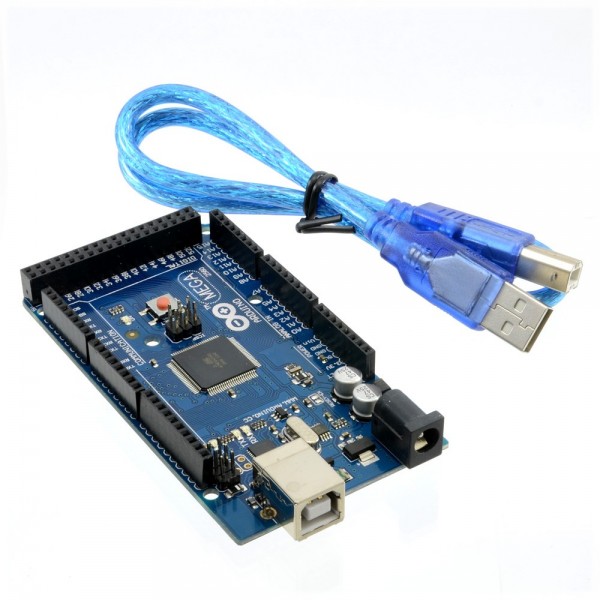
The Arduino Mega can be powered via the USB connection or with an external power supply. The power source is selected automatically.
External (non-USB) power can come either from an AC-to-DC adapter (wall-wart) or battery. The adapter can be connected by plugging a 2.1mm center-positive plug into the board's power jack. Leads from a battery can be inserted in the Gnd and Vin pin headers of the POWER connector.
The board can operate on an external supply of 6 to 20 volts. If supplied with less than 7V, however, the 5V pin may supply less than five volts and the board may be unstable. If using more than 12V, the voltage regulator may overheat and damage the board. The recommended range is 7 to 12 volts.
The power pins are as follows:
- VIN. The input voltage to the Arduino board when it's using an external power source (as opposed to 5 volts from the USB connection or other regulated power source). You can supply voltage through this pin, or, if supplying voltage via the power jack, access it through this pin.
- 5V. The regulated power supply used to power the microcontroller and other components on the board. This can come either from VIN via an on-board regulator, or be supplied by USB or another regulated 5V supply.
- 3V3. A 3.3 volt supply generated by the on-board FTDI chip. Maximum current draw is 50 mA.
- GND. Ground pins.
Memory
The ATmega1280 has 128 KB of flash memory for storing code (of which 4 KB is used for the bootloader), 8 KB of SRAM and 4 KB of EEPROM (which can be read and written with the EEPROM library).
Input and Output
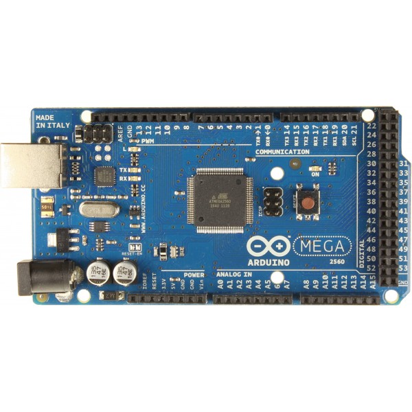
Each of the 54 digital pins on the Mega can be used as an input or output, using pinMode(), digitalWrite(), anddigitalRead() functions. They operate at 5 volts. Each pin can provide or receive a maximum of 40 mA and has an internal pull-up resistor (disconnected by default) of 20-50 kOhms. In addition, some pins have specialized functions:
- Serial: 0 (RX) and 1 (TX); Serial 1: 19 (RX) and 18 (TX); Serial 2: 17 (RX) and 16 (TX); Serial 3: 15 (RX) and 14 (TX). Used to receive (RX) and transmit (TX) TTL serial data. Pins 0 and 1 are also connected to the corresponding pins of the FTDI USB-to-TTL Serial chip.
- External Interrupts: 2 (interrupt 0), 3 (interrupt 1), 18 (interrupt 5), 19 (interrupt 4), 20 (interrupt 3), and 21 (interrupt 2). These pins can be configured to trigger an interrupt on a low value, a rising or falling edge, or a change in value. See the attachInterrupt() function for details.
- PWM: 2 to 13 and 44 to 46. Provide 8-bit PWM output with the analogWrite() function.
- SPI: 50 (MISO), 51 (MOSI), 52 (SCK), 53 (SS). These pins support SPI communication, which, although provided by the underlying hardware, is not currently included in the Arduino language. The SPI pins are also broken out on the ICSP header, which is physically compatible with the Duemilanove and Diecimila.
- LED: 13. There is a built-in LED connected to digital pin 13. When the pin is HIGH value, the LED is on, when the pin is LOW, it's off.
- I2C: 20 (SDA) and 21 (SCL). Support I2C (TWI) communication using the Wire library (documentation on the Wiring website). Note that these pins are not in the same location as the I2C pins on the Duemilanove or Diecimila.
The Mega has 16 analog inputs, each of which provide 10 bits of resolution (i.e. 1024 different values). By default they measure from ground to 5 volts, though is it possible to change the upper end of their range using the AREF pin and analogReference() function.
There are a couple of other pins on the board:
- AREF. Reference voltage for the analog inputs. Used with analogReference().
- Reset. Bring this line LOW to reset the microcontroller. Typically used to add a reset button to shields which block the one on the board.

 Maximize