 Maximize
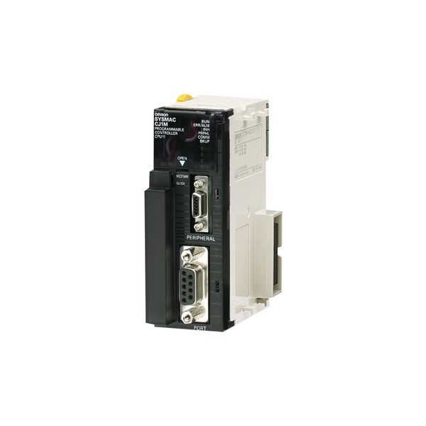
Omron CJ1M-CPU11
Call For Price01783 007 004No reward points for this product.

Maximize Call For Price01783 007 004No reward points for this product.
| Item | Specifications | |||
|---|---|---|---|---|
| Control method | Stored program | |||
| I/O control method | Cyclic scan and immediate processing are both possible. | |||
| Programming | LD (Ladder), SFC (Sequential Function Chart), ST (Structured Text), Mnemonic | |||
| CPU processing mode | CJ1M CPU Units: Normal Mode or Peripheral Servicing Priority Mode | |||
| Instruction length | 1 to 7 steps per instruction | |||
| Ladder instructions | Approx. 400 (3-digit function codes) | |||
| Execution time | CJ1M CPU Units (CPU12/13/22/23): Basic instructions: 0.10 μs min. Special instructions: 0.15 μs min. CJ1M CPU Units (CPU11/21): Basic instructions: 0.10 μs min. Special instructions: 0.15 μs min. | |||
| Overhead time | CJ1M CPU Units (CPU12/13/22/23): 0.5 ms min. CJ1M CPU Units (CPU11/21): 0.7 ms min. | |||
| Unit connection method | No Backplane: Units connected directly to each other. | |||
| Mounting method | DIN Track (screw mounting not possible) | |||
| Maximum number of connectable Units | CJ1M CPU Units: Total of 20 Units in the System, including 10 Units on CPU Rack and 10 Units on one Expansion Rack. | |||
| Maximum number of Expansion Racks | CJ1M CPU Units (CPU 13/23 only): 1 max. (An I/O Control Unit is required on the CPU Rack and an I/O Interface Unit is required on the Expansion Rack.) CJ1M CPU Units (CPU11/12/21/22): Expansion is not possible. | |||
| Number of tasks | 288 (cyclic tasks: 32, interrupt tasks: 256) With CJ1M CPU Units, interrupt tasks can be defined as cyclic tasks called "extra cyclic tasks." Including these, up to 288 cyclic tasks can be used. Note 1. Cyclic tasks are executed each cycle and are controlled with TKON(820) and TKOF(821) instructions. Note 2. The following 4 types of interrupt tasks are supported. Power OFF interrupt tasks: 1 max. Scheduled interrupt tasks: 2 max. I/O interrupt tasks: 32 max. External interrupt tasks: 256 max. | |||
| Interrupt types | Scheduled Interrupts: Interrupts generated at a time scheduled by the CPU Unit's built-in timer. (See note. 1) I/O Interrupts: Interrupts from Interrupt Input Units. Power OFF Interrupts (See note 2.): Interrupts executed when the CPU Unit's power is turned OFF. External I/O Interrupts: Interrupts from the Special I/O Units or CPU Bus Units. Note 1. CJ1M CPU Units: Scheduled interrupt time interval is 0.5 ms to 999.9 ms (in increments of 0.1 ms), 1 ms to 9,999 ms (in increments of 1 ms), or 10 ms to 99,990 ms (in increments of 10 ms) Note 2. Not supported when the CJ1W-PD022 Power Supply Unit is mounted. | |||
| Function blocks (CPU Unit with unit version 3.0 or later only) | Languages in function block definitions: ladder programming, structured text | |||
| CIO (Core I/O) Area | I/O Area | 1,280: CIO 000000 to CIO 007915 (80 words from CIO 0000 to CIO 0079) The setting of the first word can be changed from the default (CIO 0000) so that CIO 0000 to CIO 0999 can be used. I/O bits are allocated to Basic I/O Units. | The CIO Area can be used as work bits if the bits are not used as shown here. | |
| Link Area | 3,200 (200 words): CIO 10000 to CIO 119915 (words CIO 1000 to CIO 1199) Link bits are used for data links and are allocated to Units in Controller Link Systems. | |||
| CPU Bus Unit Area | 6,400 (400 words): CIO 150000 to CIO 189915 (words CIO 1500 to CIO 1899) CPU Bus Unit bits store the operating status of CPU Bus Units. (25 words per Unit, 16 Units max.) | |||
| Special I/O Unit Area | 15,360 (960 words): CIO 200000 to CIO 295915 (words CIO 2000 to CIO 2959) Special I/O Unit bits are allocated to Special I/O Units. (10 words per Unit, 96 Units max.) Note: Special I/O Units are I/O Units that belong to a special group called "Special I/O Units." Example: CJ1W-AD081 Analog Input Unit | |||
| Serial PLC Link Area (CJ1M CPU Units only) | 1,440 (90 words): CIO 310000 to CIO 318915 (words CIO 3100 to CIO 3189) | |||
| DeviceNet Area | 9,600 (600 words): CIO 320000 to CIO 379915 (words CIO 3200 to CIO 3799) DeviceNet bits are allocated to Slaves for DeviceNet Unit remote I/O communications when the Master function is used with fixed allocations. | |||
| Fixed allocation setting 1 | Outputs: CIO 3200 to CIO 3263 Inputs: CIO 3300 to CIO 3363 | |||
| Fixed allocation setting 2 | Outputs: CIO 3400 to CIO 3463 Inputs: CIO 3500 to CIO 3563 | |||
| Fixed allocation setting 3 | Outputs: CIO 3600 to CIO 3663 Inputs: CIO 3700 to CIO 3763 | |||
| The following words are allocated to the Master function even when the DeviceNet Unit is used as a Slave. | ||||
| Fixed allocation setting 1 | Outputs: CIO 3370 (Slave to Master) Inputs: CIO 3270 (Master to Slave) | |||
| Fixed allocation setting 2 | Outputs: CIO 3570 (Slave to Master) Inputs: CIO 3470 (Master to Slave) | |||
| Fixed allocation setting 3 | Outputs: CIO 3770 (Slave to Master) Inputs: CIO 3670 (Master to Slave) | |||
| Internal I/O Area | 4,800 (300 words): CIO 120000 to CIO 149915 (words CIO 1200 to CIO 1499) 37,504 (2,344 words): CIO 380000 to CIO 614315 (words CIO 3800 to CIO 6143) These bits in the CIO Area are used as work bits in programming to control program execution. They cannot be used for external I/O. | |||
| Work Area | 8,192 bits (512 words): W00000 to W51115 (W000 to W511) Controls the programs only. (I/O from external I/O terminals is not possible.) Note: When using work bits in programming, use the bits in the Work Area first before using bits from other areas. | |||
| Holding Area | 8,192 bits (512 words): H00000 to H51115 (H000 to H511) Holding bits are used to control the execution of the program, and maintain their ON/OFF status when the PLC is turned OFF or theoperating mode is changed. Note: The Function Block Holding Area words are allocated from H512 to H1535. These words can be used only for the function block instance area (internally allocated variable area). | |||
| Auxiliary Area | Read only: 7,168 bits (448 words): A00000 to A44715 (words A000 to A447) Read/write: 8,192 bits (512 words): A44800 to A95915 (words A448 to A959) Auxiliary bits are allocated specific functions. | |||
| Temporary Area | 16 bits (TR0 to TR15) Temporary bits are used to temporarily store the ON/OFF execution conditions at program branches. | |||
| Timer Area | 4,096: T0000 to T4095 (used for timers only) | |||
| Counter Area | 4,096: C0000 to C4095 (used for counters only) | |||
| DM Area | 32 Kwords: D00000 to D32767 Used as a general-purpose data area for reading and writing data in word units (16 bits). Words in the DM Area maintain their status when the PLC is turned OFF or the operating mode is changed. Internal Special I/O Unit DM Area: D20000 to D29599 (100 words × 96 Units) Used to set parameters for Special I/O Units. CPU Bus Unit DM Area: D30000 to D31599 (100 words × 16 Units) Used to set parameters for CPU Bus Units. | |||
| Index Registers | IR0 to IR15 Store PLC memory addresses for indirect addressing. Index registers can be used independently in each task. One register is 32 bits (2words). CJ1M CPU Units: Setting to use index registers either independently in each task or to share them between tasks. | |||
| Task Flag Area | 32 (TK0000 to TK0031) Task Flags are read-only flags that are ON when the corresponding cyclic task is executable and OFF when the corresponding task is not executable or in standby status. | |||
| Trace Memory | 4,000 words (trace data: 31 bits, 6 words) | |||
| File Memory | Memory Cards: Compact flash memory cards can be used (MS-DOS format). | |||
| Item | Specifications | |
|---|---|---|
| Constant cycle time | 1 to 32,000 ms (Unit: 1 ms) | |
| Cycle time monitoring | Possible (Unit stops operating if the cycle is too long): 10 to 40,000 ms (Unit: 10 ms) | |
| I/O refreshing | Cyclic refreshing, immediate refreshing, refreshing by IORF(097). IORF(097) refreshes I/O bits allocated to Basic I/O Units and Special I/O Units. With the CJ1M CPU Units, the CPU BUS UNIT I/O REFRESH (DLNK(226)) instruction can be used to refresh bits allocated to CPU Bus Units in the CIO and DM Areas whenever required. | |
| Timing of special refreshing for CPU Bus Units | Data links for Controller Link Units and SYSMAC LINK Units, remote I/O for DeviceNet Units, and other special refreshing for CPU Bus Units is performed at the following times: CJ1M CPU Units: I/O refresh period and when the CPU BUS UNIT I/O REFRESH (DLNK(226)) instruction is executed. | |
| I/O memory holding when changing operating modes | Depends on the ON/OFF status of the IOM Hold Bit in the Auxiliary Area. | |
| Load OFF | All outputs on Output Units can be turned OFF when the CPU Unit is operating in RUN, MONITOR, or PROGRAM mode. | |
| Timer/Counter PV refresh method | CJ1M CPU Units: BCD or binary (CX-Programmer Ver. 3.0 or higher). | |
| Input response time setting | Time constants can be set for inputs from Basic I/O Units. The time constant can be increased to reduce the influence of noise and chattering or it can be decreased to detect shorter pulses on the inputs. | |
| Mode setting at power-up | Possible (By default, the CPU Unit will start in RUN mode if a Programming Console is not connected.) | |
| Flash memory (CJ1M CPU Units only) | The user program and parameter area data (e.g., PLC Setup) are always backed up automatically in flash memory. (automatic backup and restore.) CPU Units with unit version 3.0 or later only: When downloading projects from CX-Programmer Ver. 5.0 or higher, symbol table files (including CX-Programmer symbol names, I/O comments), comment files (CX-Programmer rung comments, other comments), and program index files (CX-Programmer section names, section comments, or program comments) are stored in comment memory within the flash memory. | |
| Memory Card functions | Automatically reading programs (autoboot) from the Memory Card when the power is turned ON. | Possible |
| Program replacement during PLC operation | Possible | |
| Format in which data is stored in Memory Card | User program: Program file format PLC Setup and other parameters: Data file format I/O memory: Data file format (binary format), text format, or CSV format | |
| Functions for which Memory Card read/ write is supported | User program instructions, Programming Devices (including CX-Programmer and Programming Consoles), Host Link computers, AR Area control bits, easy backup operation | |
| Filing | Memory Card data and the EM (Extended Data Memory) Area can be handled as files. | |
| Debugging | Control set/reset, differential monitoring, data tracing (scheduled, each cycle, or when instruction is executed), instruction error tracing, storing location generating error when a program error occurs. | |
| Online editing | When the CPU Unit is in MONITOR or PROGRAM mode, multiple program sections ("circuits") of the user program can be edited together. This function is not supported for block programming areas. (With the CX-Programmer is used, multiple program sections of the user program can be edited together. When a Programming Console is used, the program can be edited in mnemonics only.) | |
| Program protection | Overwrite protection: Set using DIP switch. Copy protection: Password set using CX-Programmer or Programming Consoles. | |
| Error check | User-defined errors (i.e., user can define fatal errors and non-fatal errors) The FPD(269) instruction can be used to check the execution time and logic of each programming block. FAL and FALS instructions can be used with the CJ1M CPU Units to simulate errors. | |
| Error log | Up to 20 errors are stored in the error log. Information includes the error code, error details, and the time the error occurred. A CJ1M CPU Unit can be set so that user-defined FAL errors are not stored in the error log. | |
| Serial communications | Built-in peripheral port: Programming Device (including Programming Console) connections, Host Links, NT Links Built-in RS-232C port: Programming Device (excluding Programming Console) connections, Host Links, no-protocol communications, NT Links, Serial Gateway (Compoway/F master) | |
| Serial Communications Unit (sold separately): Protocol macros, Host Links, NT Links, Modbus-RTU slave, No-protocol, Serial Gateway (Compoway/F master, Modbus master) | ||
| Clock | Provided on all models. Accuracy: | |
| Ambient temperature | Monthly error | |
| 55 °C | -3.5 min to +0.5 min | |
| 25 °C | -1.5 min to +1.5 min | |
| 0 °C | -3 min to +1 min | |
| Note: Used to store the time when power is turned ON and when errors occur. | ||
| Power OFF detection time | AC Power Supply Unit: 10 to 25 ms (not fixed) DC Power Supply Unit PD025: 2 to 5 ms; PD022: 2 to 10 ms | |
| Power OFF detection delay time | 0 to 10 ms (user-defined, default: 0 ms) Note: Not supported when the CJ1W-PD022 Power Supply Unit is mounted. | |
| Memory protection | Held Areas: Holding bits, contents of Data Memory and Extended Data Memory, and status of the counter Completion Flags and present values. Note: If the IOM Hold Bit in the Auxiliary Area is turned ON, and the PLC Setup is set to maintain the IOM Hold Bit status when power to the PLC is turned ON, the contents of the CIO Area, the Work Area, part of the Auxiliary Area, timer Completion Flag and PVs, Index Registers, and the Data Registers will be saved for up to 20 days. | |
| Sending commands to a Host Link computer | FINS commands can be sent to a computer connected via the Host Link System by executing Network Communications Instructions from the PLC. | |
| Remote programming and monitoring | Host Link communications can be used for remote programming and remote monitoring through a Controller Link, Ethernet, DeviceNet, or SYSMAC LINK network. | |
| Communicating across network levels | Remote programming and monitoring from Support Software and FINS message communications can be performed across different network levels, even for different types of network. Pre-Ver. 2.0: Three levels Version 2.0 or later: Eight levels for Controller Link and Ethernet networks (See note.), three levels for other networks. Note: To communicate across eight levels, the CX-Integrator or the CX-Net in CX-Programmer version 4.0 or higher must be used to set the routing tables. | |
| Storing comments in CPU Unit | I/O comments can be stored as symbol table files in the Memory Card, EM file memory, or comment memory (see note). Note: Comment memory is supported for CX-Programmer version 5.0 or higher and CS/CJ-series CPU Units with unit version 3.0 or later only. | |
| Program check | Program checks are performed at the beginning of operation for items such as no END instruction and instruction errors. CX-Programmer can also be used to check programs. | |
| Control output signals | RUN output: The internal contacts will turn ON (close) while the CPU Unit is operating (CJ1W-PA205R). | |
| Battery life | Battery Set for CJ1M CPU Units: CJ1W-BAT01 | |
| Self-diagnostics | CPU errors (watchdog timer), I/O bus errors, memory errors, and battery errors. | |
| Other functions | Storage of number of times power has been interrupted. (Stored in A514.) | |
| Units | Models | Unit version |
|---|---|---|
| CJ1M CPU Units | CJ1M-CPU12/13 CJ1M-CPU22/23 | Unit version 4.0 |
| Unit version 3.0 | ||
| Unit version 2.0 | ||
| Pre-Ver. 2.0 | ||
| CJ1M-CPU11/21 | Unit version 4.0 | |
| Unit version 3.0 | ||
| Unit version 2.0 |
CX-Programmer 7.0 or higher must be used to enable using the functions added for unit version 4.0.
Additional functions are supported if CX-Programmer version 7.2 or higher is used.
| Function | CJ1M-CPU[][] | ||
|---|---|---|---|
| Unit version 4.0 or later | Other unit versions | ||
| Online editing of function blocks Note: This function cannot be used for simulations on the CX-Simulator. | OK | - | |
| Input-output variables in function blocks | OK | - | |
| Text strings in function blocks | OK | - | |
| New application instructions | Number-Text String Conversion Instructions: NUM4, NUM8, NUM16, STR4, STR8, and STR16 | OK | - |
| TEXT FILE WRITE (TWRIT) | OK | - | |
| ST programming in task programs | OK with CX-Programmer version 7.2 or higher | - | |
| SFC programming in task programs | OK with CX-Programmer version 7.2 or higher | - | |
User programs that contain functions supported only by CPU Units with unit version 4.0 or later cannot be used on CS/CJ-series CPU Units with unit version 3.0 or earlier. An error message will be displayed if an attempt is made to download programs containing unit version 4.0 functions to a CPU Unit with a unit version of 3.0 or earlier, and the download will not be possible.
If an object program file (.OBJ) using these functions is transferred to a CPU Unit with a unit version of 3.0 or earlier, a program error will occur when operation is started or when the unit version 4.0 function is executed, and CPU Unit operation will stop.
CX-Programmer 5.0 or higher must be used to enable using the functions added for unit version 3.0.
| Function | CJ1M-CPU[][] | ||
|---|---|---|---|
| Unit version 3.0 or later | Other unit versions | ||
| Function blocks | OK | - | |
| Serial Gateway (converting FINS commands to CompoWay/F commands at the built-in serial port) | OK | - | |
| Comment memory (in internal flash memory) | OK | - | |
| Expanded simple backup data | OK | - | |
| New application instructions | TXDU(256), RXDU(255) (support no-protocol communications with Serial Communications Units with unit version 1.2 or later) | OK | - |
| Model conversion instructions: XFERC(565), DISTC(566), COLLC(567), MOVBC(568), BCNTC(621) | OK | - | |
| Special function block instructions: GETID(286) | OK | - | |
| Additional instruction functions | PRV(881) and PRV2(883) instructions: Added high-frequency calculation methods for calculating pulse frequency. (CJ1M CPU Units only) | OK | - |
User programs that contain functions supported only by CPU Units with unit version 3.0 or later cannot be used on CS/CJ-series CPU Units with unit version 2.0 or earlier. An error message will be displayed if an attempt is made to download programs containing unit version 3.0 functions to a CPU Unit with a unit version of 2.0 or earlier, and the download will not be possible.
If an object program file (.OBJ) using these functions is transferred to a CPU Unit with a unit version of 2.0 or earlier, a program error will occur when operation is started or when the unit version 3.0 function is executed, and CPU Unit operation will stop.
CX-Programmer 4.0 or higher must be used to enable using the functions added for unit version 2.0.
| Function | CJ1M CPU Units | |||
|---|---|---|---|---|
| CJ1M-CPU12/13/22/23 | CJ1M-CPU11/21 | |||
| Unit version 2.0 or later | Other unit versions | Unit version 2.0 or later | ||
| Downloading and Uploading Individual Tasks | OK | - | OK | |
| Improved Read Protection Using Passwords | OK | - | OK | |
| Write Protection from FINS Commands Sent to CPU Units via Networks | OK | - | OK | |
| Online Network Connections without I/O Tables | OK | - (Supported if I/O tables are automatically generated at startup.) | OK | |
| Communications through a Maximum of 8 Network Levels | OK | - | OK | |
| Connecting Online to PLCs via NS-series PTs | OK | OK from lot number 030201 | OK | |
| Setting First Slot Words | OK for up to 64 groups | OK for up to 8 groups | OK for up to 64 groups | |
| Automatic Transfers at Power ON without a Parameter File | OK | - | OK | |
| Automatic Detection of I/O Allocation Method for Automatic Transfer at Power ON | OK | - | OK | |
| Operation Start/End Times | OK | - | OK | |
| New Application Instructions | MILH, MILR, MILC | OK | - | OK |
| =DT, <>DT, <DT, <=DT, >DT, >=DT | OK | - | OK | |
| BCMP2 | OK | OK | OK | |
| GRY | OK | OK from lot number 030201 | OK | |
| TPO | OK | - | OK | |
| DSW, TKY, HKY, MTR, 7SEG | OK | - | OK | |
| EXPLT, EGATR, ESATR, ECHRD, ECHWR | OK | - | OK | |
| Reading/Writing CPU Bus Units with IORD/IOWR | OK | - | OK | |
| PRV2 | OK, but only for CPU Units with built-in I/O | - | OK, but only for CPU Units with built-in I/O | |
User programs that contain functions supported only by CPU Units with unit version 2.0 or later cannot be used on CS/CJ-series Pre-Ver. 2.0 CPU Units. An error message will be displayed if an attempt is made to download programs containing unit version s.0 functions to a Pre-Ver. 2.0 CPU Unit, and the download will not be possible.
If an object program file (.OBJ) using these functions is transferred to a Pre- Ver. 2.0 CPU Unit, a program error will occur when operation is started or when the unit version 2.0 function is executed, and CPU Unit operation will stop.
The following tables show the relationship between unit versions and CX-Programmer versions.
| CPU Unit | Functions *1 | CX-Programmer | |||||
|---|---|---|---|---|---|---|---|
| Ver. 3.3 | Ver. 4.0 | Ver. 5.0 Ver. 6.0 | Ver. 7.0 or higher | Programming Console | |||
| CS/CJ-series unit Ver. 4.0 | Functions added for unit version 4.0 | Using new functions | - | - | - | OK *2 | No restrictions |
| Not using new functions | OK | OK | OK | OK | |||
| CS/CJ-series unit Ver. 3.0 | Functions added for unit version 3.0 | Using new functions | - | - | OK | OK | |
| Not using new functions | OK | OK | OK | OK | |||
| CS/CJ-series unit Ver. 2.0 | Functions added for unit version 2.0 | Using new functions | - | OK | OK | OK | |
| Not using new functions | OK | OK | OK | OK | |||
The unit version does not affect the setting made for the device type on the CX-Programmer. Select the device type as shown in the following table regardless of the unit version of the CPU Unit.
| Series | CPU Unit group | CPU Unit model | Device type setting on CX-Programmer Ver. 4.0 or higher |
|---|---|---|---|
| CJ Series | CJ1M CPU Units | CJ1M-CPU[][] | CJ1M |


» Do not allow new products at this time.
News and Events


